How it started
When I moved to France i had to re-build my home office. For my desk I opted for a local brand: kqueo. I figured that at best it was a local product and worse case scenario it was a generic re-brand for which they would be able to provide parts if needed. I picked this model: Two motors, one central control box and a panel with 3 buttons for memory position, up, down and M (to store positions) plus a 3 digit display.
A few months ago i noticed the panel, which is off most of the time unless awaken, would not awake nor move the desk. Tech support sent me a replacement right away with only my serial number, that was cool, this is when the fun begins.
As I plugged the new pannel, it immediately displayed the actual desk position and seemed to remember my memorized heights. This means that most of the logic is in the box and therefore, I could build an alternative control unit that was voice commanded.
Some forensics on the broken one
The panel looks like pretty much any other panel on the market from the outside.
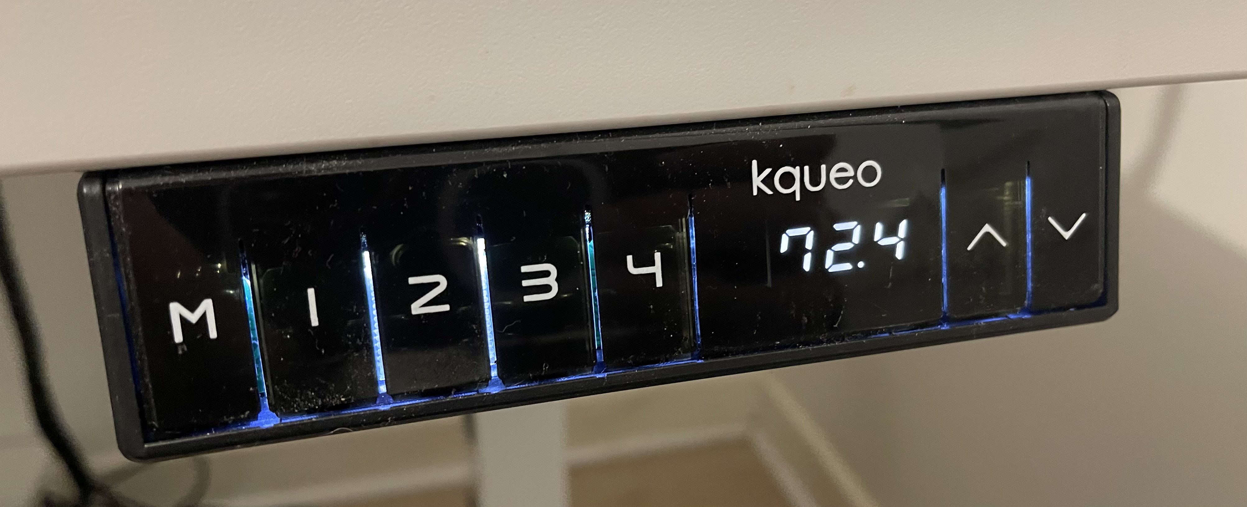
KQUEO control panel
From the inside it is fairly different
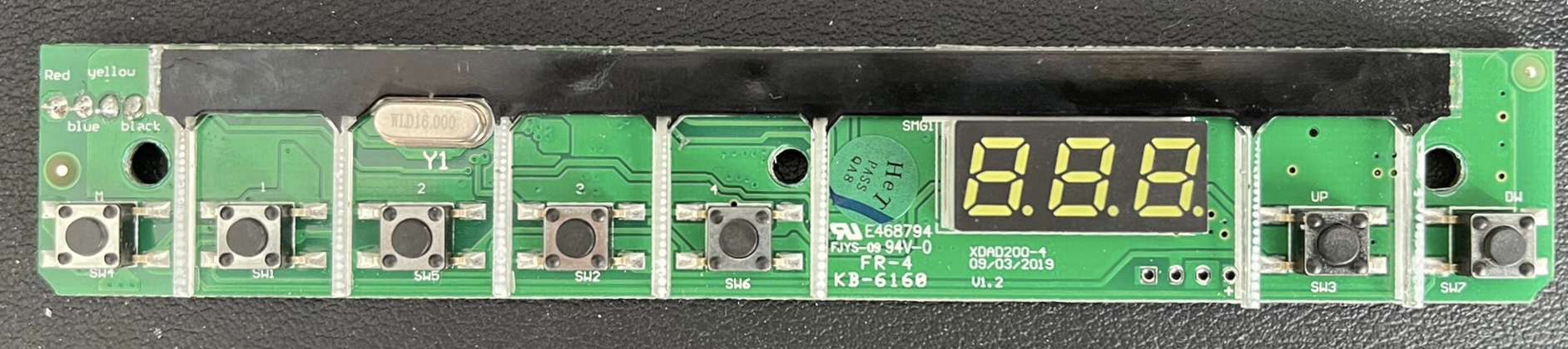
KQUEO control panel board front
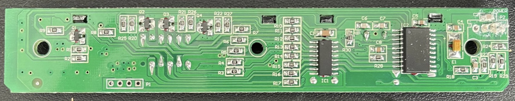
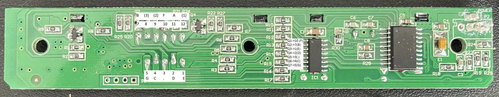
KQUEO control panel board back
The relevant components in this are:
- MC96F8208s a CMOS single-chip 8-bit MCU with 12-bit A/D converter
- 74HC595D an 8-bit serial-in, serial or parallel-out shift register with output latches
- A 3 Digit 7-Segment 11 pin display, completely generic, pinout for all on sale seems the same.
The main difference with all other models for which people have done some level of reverse engineering is that this one has only 4 wires.
- VCC (5v)
- GND
- Tx
- Rx
Some forensics on the working one.
I did not really know what TX and RX were at the time. I asked a friend that happens to be an electronics engineer expert in the field (he does consulting, dont hesitate to hire him :p). He directed me to a device that i could use to intercept what the pannel was talking with the control box and the appropriate software.
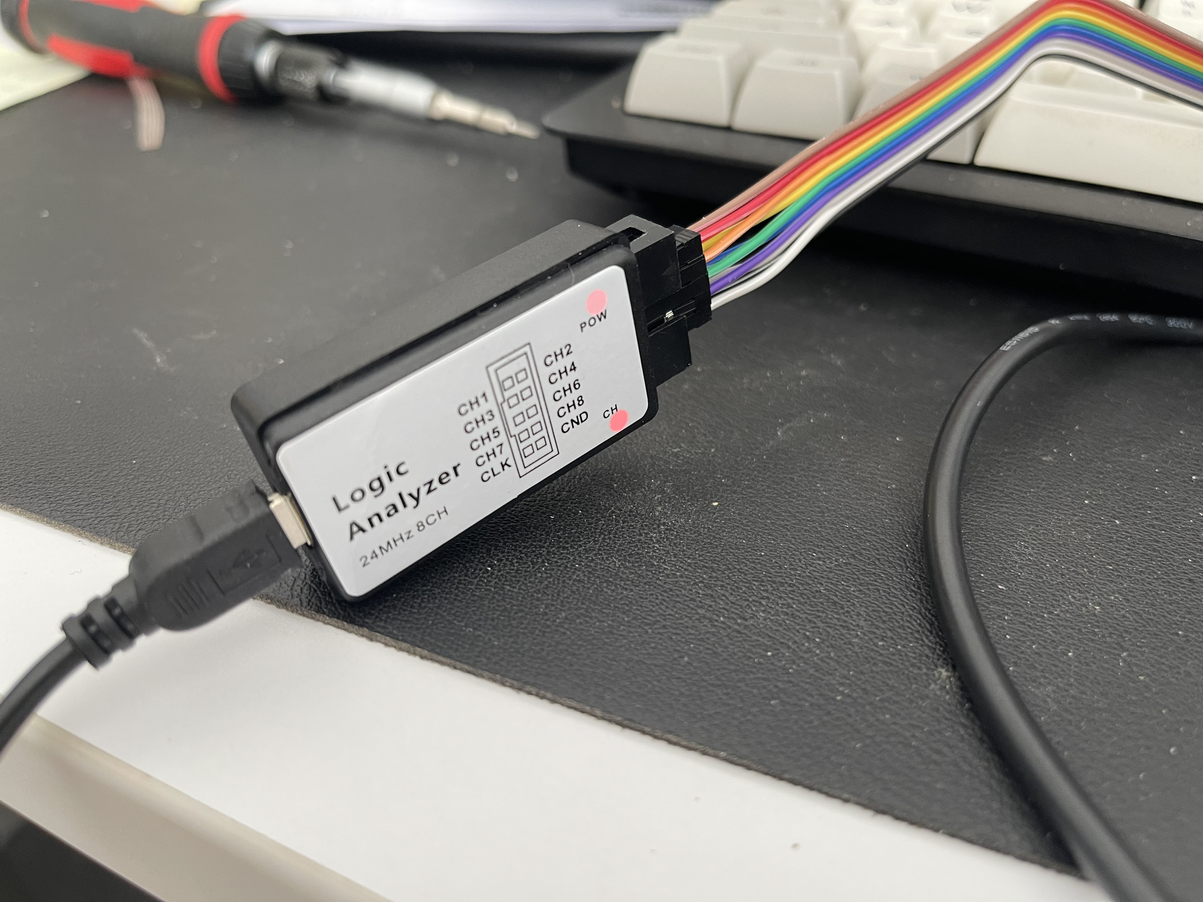
Logic Analyzer
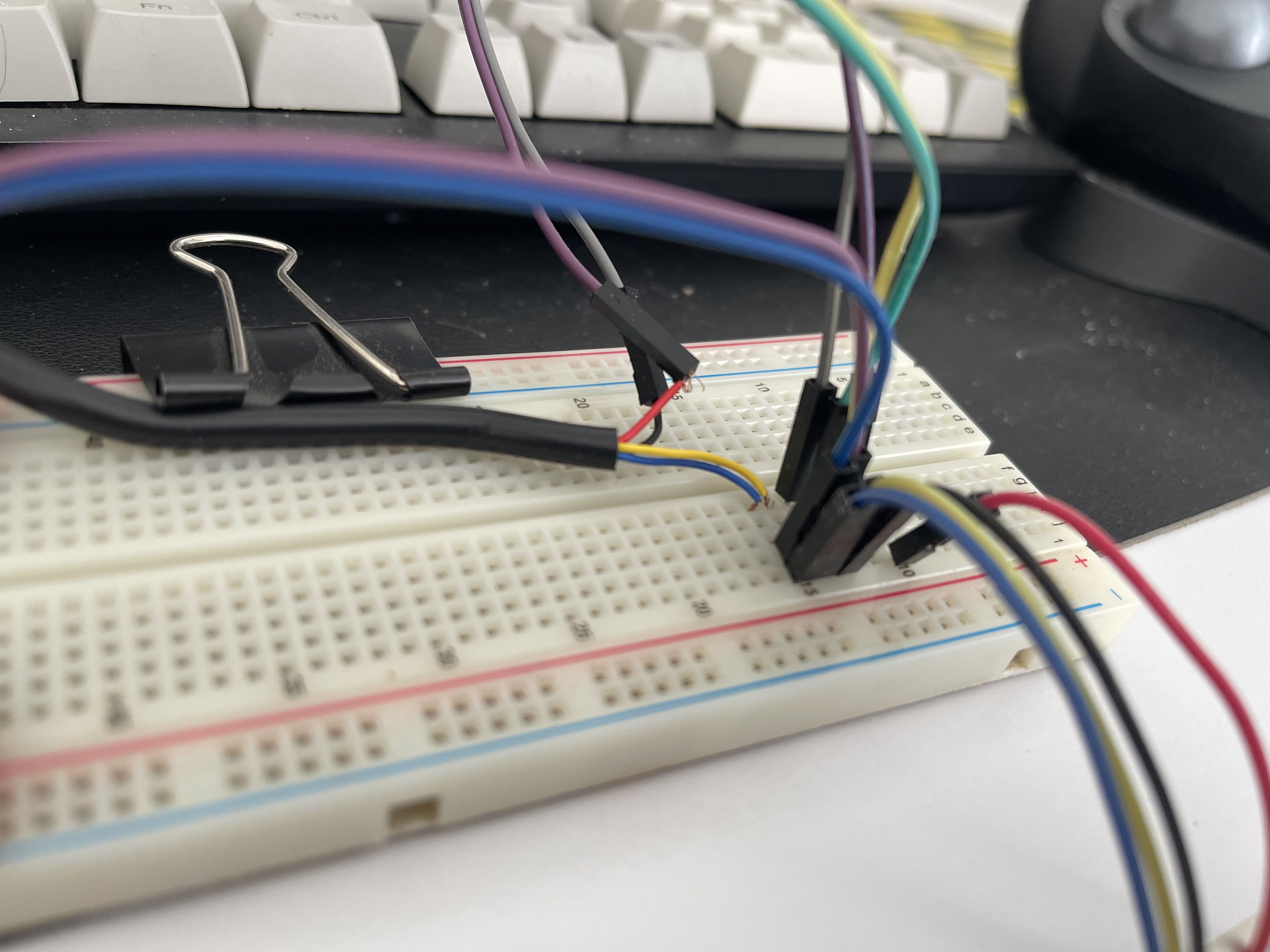
Breadboard wiring for logic analyzer
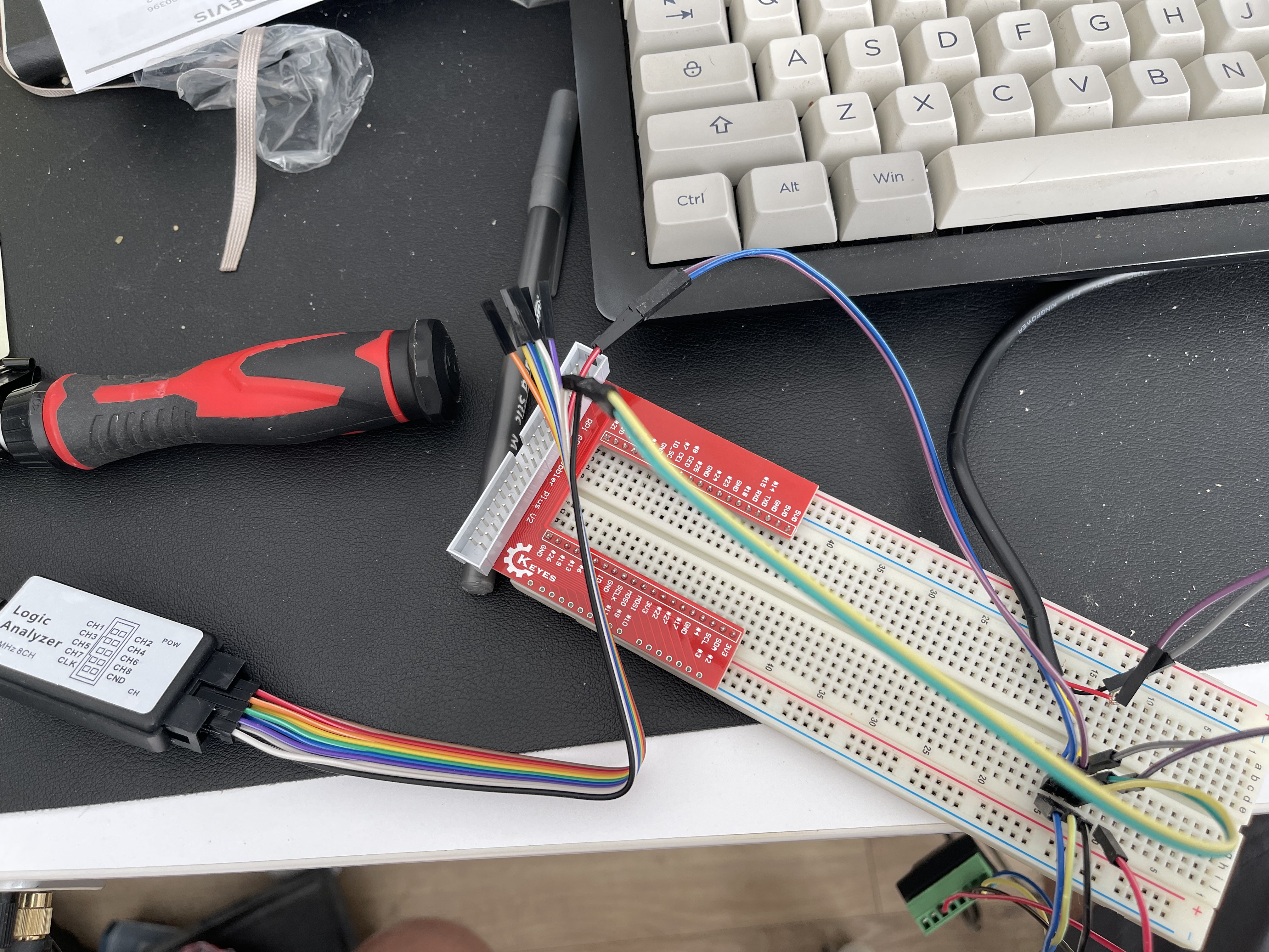
Breadboard wiring for logic analyzer
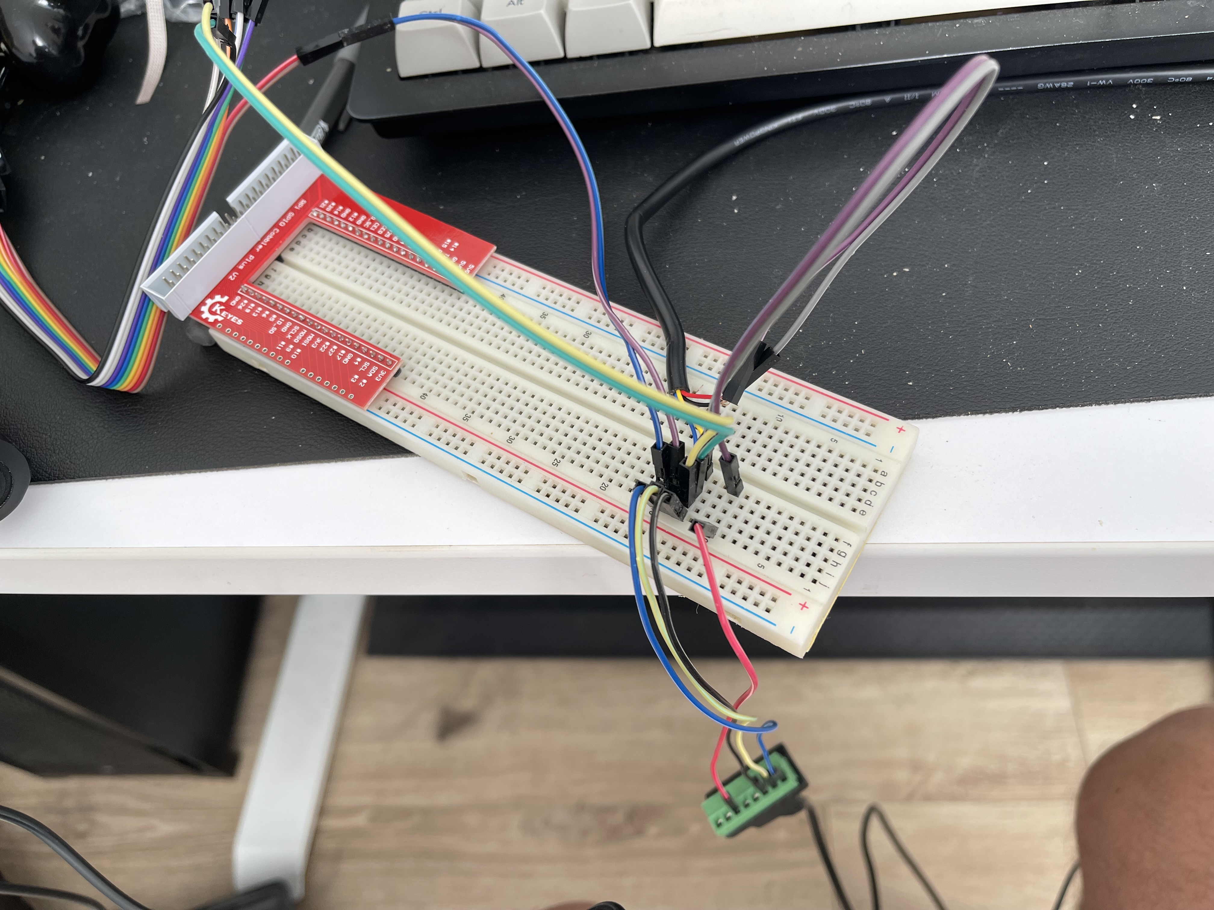
Breadboard wiring for logic analyzer
I spent a few moments going up and down in the desk while my dogs looked at me quite confused and capturing the chatter with Saleae Logic 2
I had no idea what exactly was this connection using as a protocol so I plainly guessed based on the fact that the two data pins on the cable are connected to pins 6 and 7 of the MCU which are TXD(SCL)/RXD(SDA) respectively.
Saleae allows passing the captured signal through various built in analyzers, the correct one ended up being UART over 57600 Bits/s 8 bit async serial.
Making sense of the captured data.
I captured a large chunk of data:
Now, to make sense of this data, I needed to know what the board does.
A few facts:
- The 3 Digit display is a common catode model, pins 12, 9 and 8 must be grounded to turn on digits 1, 2 and 3 respectively
- Pins 12, 9 and 8 are connected to AN10, AN8 and AN9 of the MCU respectively through a diode.
- The shift register is controlled by the MCU directly, it receives a serial 8 bits then a clk reset and it sends the data (I think)
- The leters used for the LCD pinout are the common
A-Gand.to represent the segments on a digit as depicted in this wikipedia graphic
LCD Pinout
To be continued
Assuming I mapped the circuit correctly and that I understood the protocol correctly, the only missing piece is to map the messages in the gist to the bits sent to the LCD screen.
I am currently trying to map the last line of the gist:
0xE4,0xF7,0x00,0x00,0x00,0x00,0x55,0x10,0x98,0x00,0x00,0x01,0x53,0x61
To somehow produce:
0x22,0x22,CB to be sent to the shift register